To work correctly, a custom layout file must preserve the relationship between the software layout and the physical channel order on the cap. If that relationship is changed, the layout may appear correct in the software while the underlying channel mapping no longer matches the hardware.
How layout files work
A layout text file defines how electrodes are displayed and interpreted in the software. While the labels shown in the interface are important, the row order in the file is equally important because it reflects the original channel positions. Image below shows an example of one layout file.
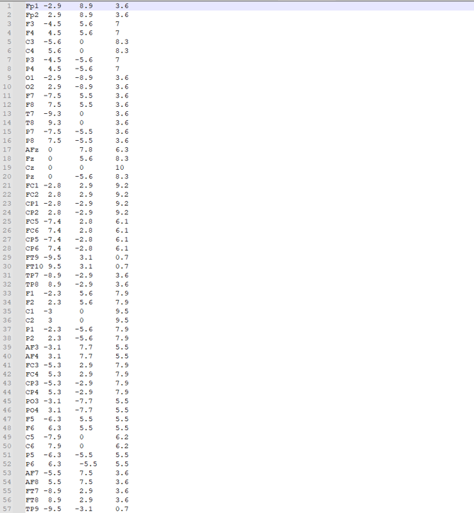
Channels have their labels and location details, which are represented in the last 3 columns.
Each row corresponds to a specific physical channel. For that reason, the original sequence of channels must remain unchanged when editing a layout file.
When to use a custom layout
A custom layout can be useful when:
-
only a subset of channels is needed for a study
-
specific electrode positions should be excluded from a recording
-
a simplified layout is preferred for a defined experimental setup
In all of these cases, the goal is to adapt the visible layout without changing the underlying hardware mapping.
Recommended approach
When creating a custom layout file, start from the original layout file provided for the system or cap.
Then:
-
Keep the original row order unchanged.
-
Leave all channel positions in place.
-
Replace channels that should not be used with NA.
-
Save the edited file as a new custom layout.
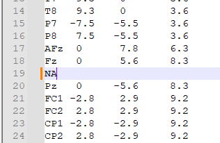
This approach preserves the original channel numbering and ensures that the electrodes you keep remain aligned with the physical cap connections.